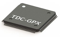
Time To Digital Converters
The TDC-GPX2 is an upgraded version of the TDC-GPX. It is more powerful, has a lower cost and smaller package than the TDC-GPX. The TDC-GPX2 is an integrated four-channel Time-to-Digital converter offering single-measurement resolution of up to 20psRMS
per channel in normal 4 channel mode. Operating in dual-channel high
resolution mode, it can achieve a maximum resolution of 10psRMS
with 5ns pulse-to-pulse spacing. The superior performance of the
TDC-GPX2 has been achieved without sacrificing power efficiency. The
GPX2 uses between 60mW and 450mW in normal operation depending on the
number of channels and update rate, and draws just 60µA in stand-by
mode.
The ScioSense TDC-GPX2 is easy to implement in end-product designs, providing standard interfaces and requires few external components. The chip also includes a driver for a quartz reference clock, which can be used for automatic calibration as an alternative to the reference clock input.
An evaluation kit is available for the TDC-GPX2, which includes a programmer and GUI software for PCs that enables customers to configure and connect their Start and Stop signals reducing the time to getting to taking sample time measurements.
ScioSense is already a leader in the LIDAR, laser scanner and 3D LIDAR market with the TDC-GPX for high precision ranging applications. The GPX2 provides even higher resolution, better precision and higher update rate that allow customers to develop systems with even higher detail and accuracy.
The TDC-GPX2 is a great upgrade from competitive technologies including the obsolete Texas Instruments (TI) THS789 Quad-Channel Time Measurement Unit (TMU).
Contact PMT Technology Center at 727-532-6144 for part availability, price and evaluation kits.
GPX | GPX2 | |
Number of channels | 2 or 8 | 2 or 4 |
Resolution @ max number of channels | 81pS | 10pS |
Inputs | TTL or LVPECL | LVDS |
Max Start Retrigger Frequency | 7 MHz | 12 MHz |
Data Output | Parallel Bus | Serial High-Speed LVDS or SPI |
Data Output Speed | 40 MHz | 600 MHz (LVDS DDR) |
Channel Data is Output | Serially: Channel 1 to 8 | All 4 Channels in Parallel |
FIFO (Each Channel) | 32 Stage | 16 Stage |
Calibration | Resolution Adjust Mode | Reference Measurement |
Double Pulse Resolution on Same Channel | 5.5nS | 4nS or 1nS (2 Channel Mode) |
Start Retrigger Number | 8 Bits | Configurable up to 24 bits |
Time Stamp | 16 Bits | Configurable up to 24 bits |
Package | TQFP100, TFBGA120 | QFN64 |
CUSTOMER-SPECIFIC INTEGRATED TDCs
The use of pure digital circuit design makes it easy to build on the performance features of the standard products and improve specific technical data. Accordingly, ScioSense develops optimized TDC's which are tailored to the specific measuring requirements of the customer.
The wealth of experience ScioSense has gathered assures the ability to integrate all necessary functions on a single circuit and so to provide a system-on-chip solution.
TDC-S1 is a TDC with 25ps standard deviation for use in the ATV (Automatic Transport Vehicle) that will supply the ISS (International Space Station). The high resolution is all the more impressive as this TDC is realized on a radiation hard process.
DFA1 Integrated circuit for detection of the rotation of a propeller meter with extremely low current consumption (<2uA) - contacless, non-magnetic und feedbackless.
On the base of the ATMD-System we also develop complete solutions and additional modules to fit your application.
Take as an example the AM-HM1 histogramming module, that was developed for RoentDek. This is a standalone PC-based 4-channel TDC with 32MB Histogram memory for fast readout of Delay-Line-Detectors developed by RoentDek. For more information, please contact RoentDek.
Another example is the Time-of-Flight Module offered by GPTA (Gesellschaft für physikalisch-technische Anwendungen). The key features of this module are virtually dead time free operation, 5 ns multihit dead time in 1 channel mode, (60±5) ps maximum resolution, an input for multicard coincidence measurements. For more information, please email sales@gpta.de
Description | Version | Size | Download |
---|---|---|---|
Datasheet TDC-GP22 Eval System: Preliminary datasheet for TDC-GP22 evaluation system | V0.2 | 5.3MB | DB_GP22-EVA_en.pdf |
Datasheet TDC-GP22: Datasheet for TDC-GP22 Time-to-Digital Converter | V0.9 | 4MB | |
Datasheet TDC-GP21 Eval System: Preliminary datasheet for TDC-GP21 evaluation system | V0.2 | 5.3MB | |
Datasheet TDC-GP21: Datasheet for TDC-GP21 Time-to-Digital Converter | V1.6 | 4MB | |
Datasheet TDC-GPX: ATMD evaluation system for TDC-GPX (DISCONTINUED) | 1.3MB | ||
Datasheet TDC-GP2: 2-channel TDC 65 ps | V2.0 | 2.6MB | |
Datasheet TDC-GPX2 Eval System: Preliminary datasheet for TDC-GP22 evaluation system | V0.2 | 2948kB | |
Datasheet TDC-GPX2: 4-Channel Time-to-Digital Converter | V0.2 | 1979kB | |
Datasheet TDC-GPX: 8-channel TDC 81 ps, 2-channel TDC 41 ps/27 ps/10 ps | V0.2 | 800kB |
Description | Version | Size | Download |
---|---|---|---|
Application Note 034: Laser Range Finder with the TDC-GP22 | V1.3 | 837kB | AN034_en.pdf |
Application Note 027: TDC-GP2 to TDC-GP21 Migration and Compatibility Guideline | V0.1 | 400kB | AN027_en.pdf |
Application Note 024: Metrological Investigations of TDC-GP2 Temperature Measurement Unit | V1.0 | 1.2MB | AN024_en.pdf |
Application Note 016: TDC-GPX Reduced Decoupling | 73kB | AN016_en.pdf | |
Application Note 013: TDC-GPX - PLL Regulation Circuit | V3.0 | 100kB | AN013_en.pdf |
Description | Version | Size | Download |
---|---|---|---|
Software TDC-GPX2: Evaluation software package for GPX2 (incl. doc, cfg, drv) | V1.0.5 | 206MB | CD-GPX2-EVA.zip |
Software TDC-GP22: STM32 µC Sample code of Application Note 034 | 42kB | GP22_main_AN034.c | |
Software TDC-GP22: Software package for GP22-EVA-KIT | V1.9 | 111MB | CD-GP22-EVA-XP-WIN7.zip |
Software TDC-GP21 Software package for GP21-EVA-KIT | V3.9 | 104MB | CD-GP21-EVA-XP-WIN7.zip |
Software TDC-GPX: Evaluation software for ATMD-GPX | V4.0 | 18MB | ATMD-GPX.zip |
Software TDC-GPX: Visual-C++ sample code for ATMD-GPX | 214kB | ATMD-GPX-C-samples.zip | |
Software ATMD-PCI: Driver files for ATMD-PCI interface card | 2kB | AcamAtmdPci.zip | |
Software PICOPROG V3.0 (V2.0): Driver Installer Stand-Alone | R11 | 5MB | PicoProg_v2_Driver_Installer_Stand-Alone.zip |
Software National Instruments: NI VISA instrument drivers | V3.0 | 12MB | ni-visa.zip |
Software National Instruments: NI VISA runtime engine for Windows 7 | V4.62 | 53MB | visa462runtime.exe |
Software National Instruments: NI VISA runtime engine for Windows Vista | V4.1 | 41MB | visa410full.exe |
Software National Instruments: NI VISA runtime engine for Windows XP | V3.2 | 14MB | visa320runtime.exe |
Software National Instruments: NI VISA runtime engine for Windows 98 | V2.6 | 8MB | visa260runtime.exe |
Description | Version | Size | Download |
---|---|---|---|
PCN/PDN TDC-GP1 Pd-free package | V1 | 67kB | PCN0104.pdf |
PCN/PDN TDC-F1 Pb-free package | V1 | 49kB | PCN0204.pdf |
PCN/PDN TDC-F1 Discontinuation of production | V1 | 68kB | PDN0711-01.pdf |
PCN/PDN ATMD-GP1 Discontinuation of production | V1 | 34kB | PDN1009-01.pdf |
INTEGRATED DIGITAL TIME-TO-DIGITAL CONVERTERS
Digital delay time TDCs are integrated circuits for high precision time interval measurement and do this without any analog components. They became real thanks to the innovations in semiconductor technology made over the years. They use the propagation delays of simple logical gates (i.e. inverters) for fine quantization of time intervals. Due to the enormous achievements in signal speed, especially in the CMOS sector, it has become possible to implement
such TDCs in standard CMOS technology with a resolution in the picosecond range. Nowadays we can integrate system solutions into a single chip that are efficient, power saving, space saving and none the less low price.
Digital TDCs can be split into two groups:
ABSOLUTE DELAY TIME TDC
This type of TDC uses the absolute propagation time of signals through simple logical elements for fine quantisation of time intervals. (see figure below)
In other words, it determines how many inverter cycles the measured time interval consists of. The figure shows the principle of operation. Clever circuit set-ups, redundant elements and special layout methods on the chip enable the exact reconstruction of the number of basic time intervals. The resolution strictly depends upon the basic delay time in the chip. Resolutions in the range of 14 -100 ps can be achieved by a simple set-up of the measuring core and the use of a state-of-the art CMOS process. The propagation delay itself depends on temperature and supply voltage. Therefore the measured value must be calibrated. This is done by measuring one and two periods of a reference oscillator. Ideally this measurement and the following calculation is done by the TDC itself.
Absolute delay time TDCs have the following advantage:
Laser Distance Meters Application
Ultrasonic Flowmeter Application
Ultrasonic Density Meter Application
Ultrasonic Thickness Meter Application
Type | Part number | Package | RoHS compl. | Shipping package |
---|---|---|---|---|
TDC-GP22: | ||||
TDC-GP22 | MNR 1949 | QFN32 | Yes | Tray |
TDC-GP22 | MNR 1950 | QFN32 | Yes | Tape & Reel (5k) |
GP22-EVA-KIT | MNR 1951 | System | Yes | Box |
GP22-DEMO-KIT | MNR 1979 | System | Yes | Box |
TDC-GP21: | ||||
TDC-GP21 | MNR 1839 | QFN32 | Yes | Tray |
TDC-GP21 | MNR 1720 | QFN32 | Yes | Tape & Reel (3K/5K) |
GP21-EVA-KIT | MNR 1781 | System | Yes | Box |
TDC-GP2: | ||||
TDC-GP2 | MNR 1058 | QFN32 | Yes | Tray |
TDC-GP2 | MNR 1480 | QFN32 | Yes | Tape & Reel (2k) |
TDC-GPX: | ||||
TDC-GPX | MNR 975 | TQFP100 | Yes | Tray |
TDC-GPX-FG | MNR 1089 | TFBGA120 | Yes | Tray |